Fuel dispenser downtime immediately disrupts station profitability. Every offline pump frustrates drivers, reduces daily throughput, and introduces potential safety risks to your forecourt. Station operators cannot afford prolonged maintenance windows.
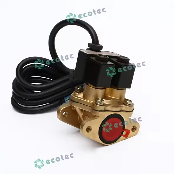
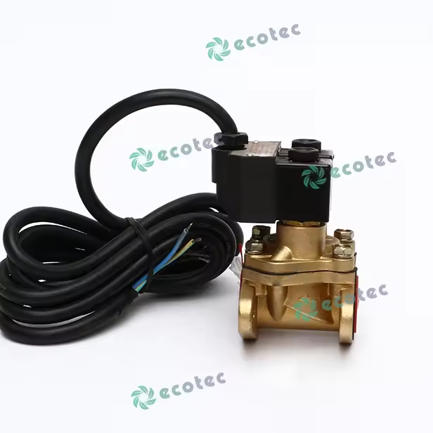
At the heart of this system sits the solenoid valve. It acts as the critical gatekeeper between the pumping unit and the dispensing nozzle. When this component fails, stations face unauthorized fuel flow, agonizingly slow dispensing, or catastrophic fluid leaks. Recognizing these failure patterns quickly saves both time and money.
We will explore an evidence-based framework for diagnosing and repairing these malfunctions. You will learn how to isolate root causes, execute step-by-step inspections, and evaluate replacement options. This guide equips maintenance managers to restore operations quickly, safely, and permanently.
Key Takeaways
Not all flow issues are valve failures; isolating communication errors from the fuel controller or calibration issues in the flow meter is step one.
"Slow flow" and "failure to shut off" are the two highest-risk symptoms, often requiring immediate mechanical inspection or electrical continuity testing.
The decision to repair versus replace hinges on downtime costs, labor rates, and the lifecycle stage of your existing dispenser hardware.
Sourcing OEM or certified aftermarket fuel dispenser accessories prevents recurring failures and ensures compliance with hazardous location regulations (e.g., ATEX, UL).
Isolating the Issue: Is It Actually the Solenoid Valve?
Before tearing down hardware, you must verify the actual source of the malfunction. Technicians frequently misdiagnose dispenser issues, replacing functional valves when the true culprit lies elsewhere in the hydraulic or electronic system.
Symptom Mapping Guide
| Operational Symptom | Probable Root Cause | Recommended First Action |
| Continuous dripping from nozzle | Debris on valve seat or degraded O-ring | Perform pressure test with valve closed |
| Unauthorized dispensing | Stuck open armature or relay failure | Disconnect power to isolate electrical fault |
| Complete flow failure | Burnt-out coil or lack of supply voltage | Test coil resistance with a multimeter |
Next, perform a system integration check. The solenoid valve rarely operates in isolation. You must understand how the fuel controller dictates the valve's dual-stage operation. Modern dispensers use a high-flow and low-flow stage. The controller sends specific voltage signals to open the primary port for maximum throughput, then drops to the secondary port to slow the flow before hitting the preset transaction amount. If the controller fails to send this step-down signal, the valve will not operate correctly.
Similarly, you must rule out a malfunctioning flow meter. A meter measures fluid volume precisely but does not control the physical stop or start of the liquid. If your calibration tests show volume discrepancies without flow leakage, the meter likely requires adjustment, not the valve.
Finally, distinguish between electrical and mechanical failures. An electrical failure usually involves a burnt-out coil or a severed wiring connection. This stops the magnetic field generation entirely. A mechanical failure involves physical blockages. Ruptured diaphragms, swollen seals, or debris stuck in the pilot hole prevent the internal mechanisms from moving, even when the coil receives perfect voltage.
Addressing Common Solenoid Valve Failures (Visual & Functional)
You will encounter three primary failure modes in the field. Identifying these visually and functionally accelerates the repair process.
Slow Dispensing Flow Rates
Customers quickly complain when a pump takes twice as long to fill their tank. Several hidden factors cause this frustrating issue.
Causes: Clogged pilot holes restrict the internal pressure equalization required to open the main diaphragm fully. Deteriorating diaphragms lose their flexibility, preventing maximum lift. Alternatively, a failing coil provides a weak magnetic pull, only partially opening the armature.
Diagnostics: Always verify pump pressure first. If the submersible turbine pump delivers standard pressure to the dispenser base, the restriction lives in the hydraulic block. Inspect the valve's internal strainer for particulate buildup. Clean any debris from the pilot orifice using compressed air.
Oil Leakage and Seeping
Visible fuel leaks create immediate fire hazards and environmental compliance violations. You must address seeping instantly.
Causes: Degraded O-rings lose their sealing ability over time. Debris caught between the piston and the valve seat prevents proper closure. Thermal expansion fatigue also warps aluminum housings during extreme temperature fluctuations.
Diagnostics: Perform a careful visual inspection of the valve housing and the external weep holes. Look for wet spots or varnish buildup indicating slow, long-term evaporation. Pressure-test the line while the valve remains electronically closed. If pressure drops, fluid is bypassing the internal seals.
Failure to Close (Over-dispensing)
Over-dispensing leads to massive inventory shrinkage and dangerous spills. This happens when the valve fails to shut off at the transaction limit.
Causes: A broken return spring cannot push the armature back into the closed position. Sticky armatures, coated in fuel varnish, jam inside the guide tube. Sometimes, residual voltage from a faulty solid-state relay keeps the coil energized.
Diagnostics: Disconnect the power completely from the dispenser head. If fuel flow continues, you face mechanical binding. The spring or armature has physically jammed. If the flow stops immediately upon power removal, the issue sits upstream in the electrical relays or controller boards.
Step-by-Step Solenoid Valve Troubleshooting Framework
Guesswork wastes labor hours and risks catastrophic mistakes. Follow this phased, systematic framework to troubleshoot safely and accurately.
Phase 1: Safety and Isolation
Never bypass safety protocols when working with hazardous liquids and high-voltage electronics.
Initiate strict lockout/tagout (LOTO) procedures at the main breaker panel. Secure the dispenser power so nobody can accidentally energize the circuits while you work.
Isolate the specific hydraulic zone. Close the shear valves at the base of the dispenser.
Safely depressurize the fuel line. Drain residual fuel into an approved containment vessel. This prevents pressurized spray or injury during your physical inspection.
Phase 2: Electrical Diagnostics
Before opening the fluid pathways, test the external electronics.
Grab a calibrated digital multimeter. Test the coil resistance (measured in Ohms). Compare your reading against the manufacturer's specific baselines. A reading of infinity indicates an open circuit or broken wire. A reading near zero indicates a dead short.
Switch the multimeter to read AC or DC voltage, depending on your system requirements. Check for proper supply voltage from the dispenser’s power board while a transaction is authorized.
Rule out voltage drops caused by corroded wiring harnesses or loose terminal connections. Low voltage creates coil chatter and weak operation.
Phase 3: Mechanical Teardown & Inspection
If the electrical tests pass, you must investigate the internal mechanics.
Begin the step-by-step disassembly of the valve body. Remove the retaining clip or top nut. Slide the coil off the enclosing tube.
Unbolt the bonnet housing. Lift out the internal components carefully, noting their orientation for reassembly.
Inspect the piston, diaphragm, spring, and O-rings. Look for deep scoring on the metal surfaces. Check the rubber components for tears, brittleness, or chemical degradation. Swelling often occurs from aggressive fuel additives or improper ethanol blends.
The Decision Framework: Repair vs. Valve Replacement
Once you identify a mechanical failure, you face a critical operational choice. Should you rebuild the existing unit or install a brand-new valve assembly? Making the wrong choice increases maintenance frequencies and erodes profit margins.
First, conduct a cost-to-benefit analysis based on direct expenses. Compare the purchase cost of a rebuild kit, which includes fresh diaphragms, springs, and seals, against the cost of a complete drop-in replacement valve. Rebuild kits appear cheaper upfront. However, you must factor in labor time. Rebuilding a valve on the forecourt takes significantly longer than swapping a complete assembly. If your station experiences high traffic, the revenue lost during extended downtime quickly outweighs the savings of a simple parts kit.
Next, consider risk mitigation. Rebuilding aged valves introduces hidden liabilities. Aluminum housings develop micro-fractures over years of pressurized service. Guide tubes become internally scored, which new seals cannot fix. If you install a rebuild kit into a compromised housing, you guarantee repeated maintenance calls within a few months. Age matters. If the valve has operated for five years or processed millions of liters, full replacement minimizes future risk.
Finally, look at scalability and standardization. For multi-site operators, managing inventory across dozens of locations requires efficiency. Replacing whole units allows you to maintain consistent parts inventory and guarantees full manufacturer warranty coverage. Rebuilt units carry no warranty on the housing or older components. Standardization simplifies training for your maintenance crews and accelerates their diagnostic routines across all locations.
Evaluating and Sourcing Fuel Dispenser Accessories
Selecting the right components directly impacts site safety and regulatory standing. You cannot compromise on quality when dealing with combustible liquids.
Compliance and certifications form your non-negotiable baseline. Every component installed inside a fuel dispenser must carry intrinsically safe, explosion-proof ratings. These ratings must suit your specific regional requirements. Look for ATEX certifications in Europe, IECEx for international standards, or UL listings in North America. Installing uncertified parts violates fire codes and instantly voids site insurance policies.
Material compatibility is equally vital. Ensure the selected valve and its internal seals are rated for the specific fuel type being dispensed. Standard gasoline requires different elastomers than high-ethanol E85 or aggressive Biodiesel blends. For instance, Viton seals offer excellent resistance to standard fuels but may fail rapidly if exposed to certain specialized chemical additives. Always verify the manufacturer's chemical compatibility charts before procurement.
Lastly, evaluate vendor trust factors. You rely on your suppliers to keep your stations running. Look for robust warranty terms, accessible technical support, and strict traceability of parts. Realistic lead times prevent you from hoarding excessive inventory. Source OEM or certified aftermarket fuel dispenser accessories from established partners. Warn your purchasing teams against "universal fit" claims found on discount supply sites. These cheap alternatives frequently lack verifiable testing data and fail prematurely under commercial station pressures.
Conclusion
Accurate, phased troubleshooting minimizes diagnostic guesswork and accelerates return-to-service times for your fuel dispensers.
Always isolate electrical faults from mechanical blockages before tearing down the hydraulic block.
While rebuild kits serve as viable short-term fixes, full component replacements often yield better long-term returns by preventing repeat failures.
Source only certified, fuel-compatible components to maintain stringent hazardous location safety standards.
Consult the technical specifications for your specific dispenser model today, or contact a certified sales engineer to secure the appropriate replacement parts for your network.
FAQ
Q: How often should a fuel dispenser solenoid valve be inspected?
A: You should conduct basic visual and operational inspections annually. For high-volume stations, schedule preventative maintenance based on throughput milestones, typically every one to two million liters. Regular checks help identify minor weeping or slow response times before they escalate into complete failures.
Q: Can a faulty solenoid valve cause discrepancies in the flow meter reading?
A: While the valve does not measure the fuel itself, a malfunctioning valve impacts testing. If the valve fails to shut off precisely at the preset limit, it causes calibration testing to fail. It also results in unauthorized over-dispensing, making the meter's accurate reading irrelevant to the final output volume.
Q: Why is my solenoid valve humming or buzzing loudly?
A: Loud buzzing, known as AC coil chatter, indicates the armature cannot seat fully. This usually stems from debris trapped on the armature face. It can also be caused by low supply voltage failing to hold the magnetic field, or a broken shading coil inside the unit.
Q: Are dual-stage and single-stage solenoid valves interchangeable?
A: No, they are not interchangeable. Dual-stage valves are explicitly required for the precise slow-down function at the end of a preset fuel transaction. Using a single-stage valve in a dual-stage system will cause severe hydraulic shock and constant over-dispensing at the end of customer transactions.


